You are here: Foswiki>CdiDocs Web>932RearPanel (19 Mar 2025, BenDugan)Edit Attach
FIU-932: REAR PANEL CONNECTIONS

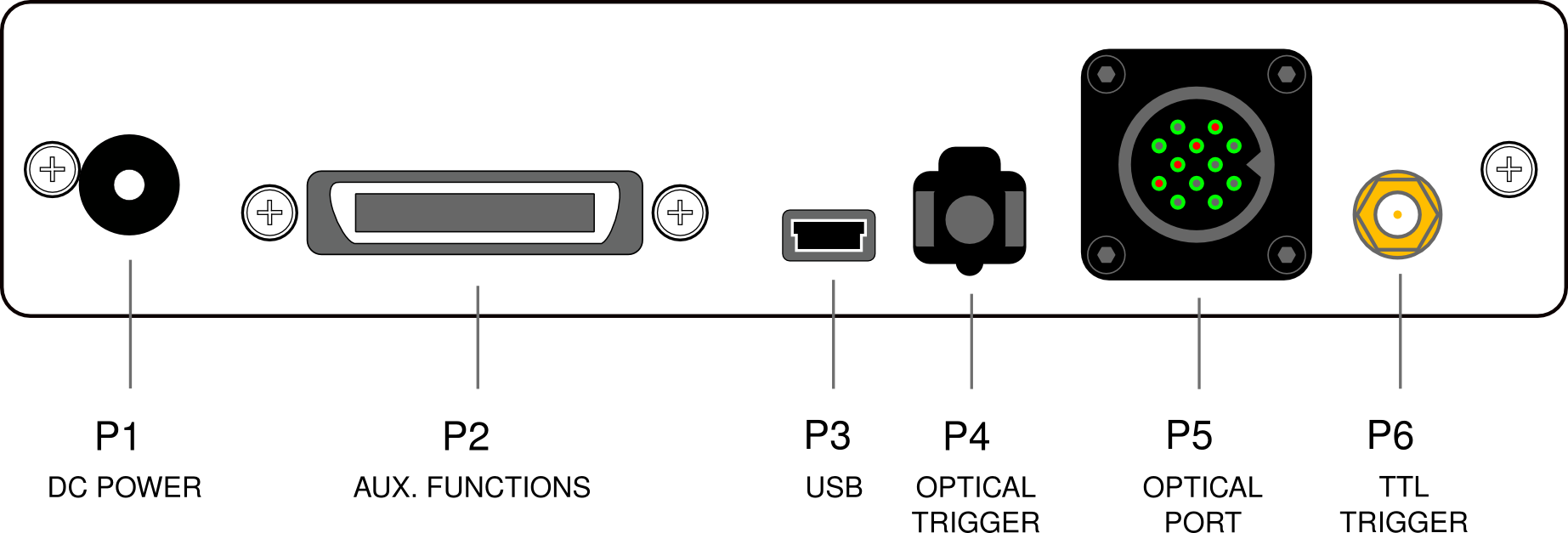
P1: DC POWER INPUT
This input should only be used with the power supply provided: PS-932-6V-INT.The 6V regulated power supply for FIU-932 is CE marked and is provided with a plug for US/Japan, EU, UK or Australia.
P2: AUXILLARY FUNCTIONS - SERIAL AND TTL OUTPUTS
This port contains the TTL and serial output signals.- For the serial output, use cable CB-932-SER-1.
- For use with a parallel port, use cable CB-932-PAR-1.
- For a TTL trigger output, use CB-932-TRIGO-1.
- For other cables see the accessories page.
P3: USB OUTPUTS
For most users this is the main data output port. It is connected to the host computer using a commonly available USB cable (5 pin mini-USB to USB).P4: OPTICAL TRIGGER INPUT
This port accepts optical trigger signals such as those produced on some Siemens MR scanners. It uses an Agilent HFBR connector.Use with cable HFBR-RNS010Z or an equivalent.
P5: OPTICAL PORT
This port connects to a Current Designs removable fiber optic bundle or directly to an optical handheld device. It has 12 optical pins: 4 transmitting and 8 receiving.P6: TTL TRIGGER INPUT
This connector accepts TTL trigger signals. Triggers are detected on low-to-high (positive-going) edges; there is no minimum pulse width.Use with cable CB-SMB-BNC-1 or an equivalent/
Edit | Attach | Print version | History: r2 < r1 | Backlinks | View wiki text | More topic actions
Topic revision: r2 - 19 Mar 2025, BenDugan
 Copyright © by the contributing authors. All material on this collaboration platform is the property of the contributing authors.
 Ideas, requests, problems regarding Foswiki? Send feedback


